ECGbook.com

Making Medical Education Free for All

ECGbook.com

Making Medical Education Free for All

Home /

Electrical Axis of the Heart

Heart electrical (QRS) axis

Ventricular Depolarization

Mean frontal plane electrical QRS axis
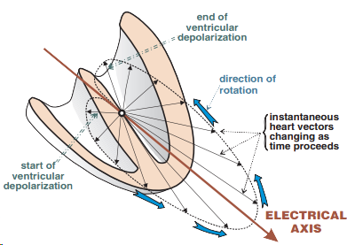
  • The ventricular myocardium depolarizes gradually
  • Depolarization creates an electrical vector
  • The more cardiomyocytes depolarize
    • The larger the electrical vector becomes

  • Summation Electrical Vector
    • Each cardiomyocyte creates a vector during depolarization
    • The common direction of vectors during depolarization
      • Is referred to as the summation electrical vector
  • Summation Vector of the Left Ventricle:
    • Is the resultant direction of depolarization vectors
      • Of all cardiomyocytes in the left ventricle
    • Is the largest vector
      • Because it involves the depolarization of the largest mass of myocardium
    • Its direction determines the electrical axis of the heart
  • The summation vector during ventricular depolarization

Electrical Axis of the Heart

Heart axis vector during ventricular depolarization

ECG Leads

Heart axis vector with ECG leads
  • An ECG recording has 12 leads
    • Limb leads (I, II, III, aVF, aVL, aVR)
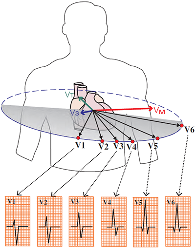
    • Chest leads (V1-V6)
    • Each lead "views" the vectors from a different angle
  • Leads "view" the electrical center of the heart
  • If the electrical vector points
    • Toward the lead on the surface - a positive deflection occurs
    • Away from the lead on the surface - a negative deflection occurs


Limb ECG Leads

Frontal plane electrical QRS axis and limb leads

Electrical Axis of ECG Leads

Lead axis and determination of the electrical axis of the heart
  • Each ECG lead has its own electrical axis
  • The main cardiac vector projects onto the electrical axes of all ECG leads
    • Each electrical vector of the heart projects onto the electrical axes of ECG leads
      • However, the cardiac axis is determined solely by the main electrical vector (from the depolarization of the left ventricle)

  • When determining the electrical axis of the heart, we only consider
    • the limb ECG leads (I, II, III, aVF, aVR, aVL)

Positive and Negative ECG Deflections

Mechanism of determining heart axis via QRS complex deflection

Size of the ECG Deflection

Heart axis principle with ECG electrical axis lead
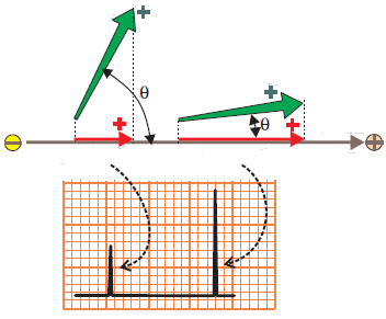
  • The size of the ECG deflection
    • depends on the angle between the vector and the ECG lead axis

  • The smaller the angle
    • the more directly the vector points towards the electrode (+)

Isoelectric ECG Deflection

Perpendicular voltage vector and determination of heart axis

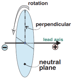
Neutral Plane

Perpendicular electrical vector and neutral plane. Determination of heart axis
  • When a perpendicular electrical vector
    • Is rotated in 3D space around the electrical axis of the lead
    • It creates the neutral plane of the given ECG lead
  • Every vector in the neutral plane
    • Projects onto the electrical axis of the ECG lead as a single point
    • No deflection appears on the ECG

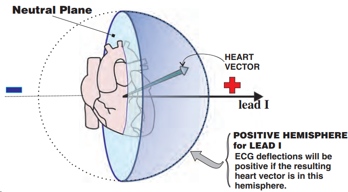
Positive and Negative Hemispheres of ECG Leads

Positive hemisphere for lead I. ECG deflections will be positive if the resulting heart vector is in this hemisphere

Heart axis determination with electrical vector negative deflection

Negative Hemisphere and Negative Deflection

  • Negative deflection occurs
    • Whenever the vector points away from the (+) electrode
    • The electrical axis of the lead continues beyond the electrical center of the heart (-)
  • Size of the deflection
    • Depends on the size of the vector that is projected onto the electrical axis of the ECG lead
    • Does not depend on the distance of the vector from the (+) electrode
  • Both vectors in the image produce the same ECG deflection


Heart axis determination with electrical vector positive deflection

Positive Hemisphere and Positive Deflection


QRS Complex and Electrical Heart Axis

Heart axis vector during ventricular depolarization
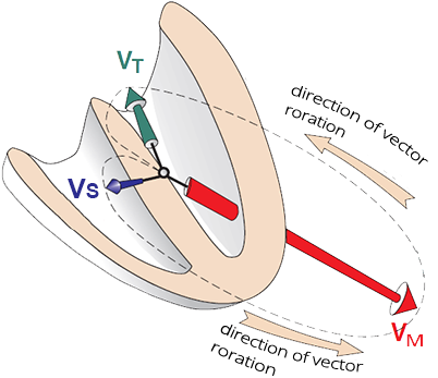
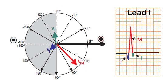
  • During ventricular depolarization, 3 main vectors are formed
    • Initial vector (Q wave)
      • Depolarization of the septum
    • Main vector (R wave)
      • Depolarization of the left ventricle
    • Terminal vector (S wave)
      • Depolarization of the base of the left ventricle
  • The vectors are simultaneously "viewed" by the ECG leads
    • However, each lead "views" the vectors from a different angle
    • Each vector is projected onto the electrical axis of the ECG leads

  • The electrical axis of the heart is determined by the direction of the main electrical vector

I Lead

Heart axis determination in positive hemisphere of I limb lead

I Limb Lead


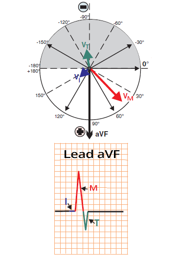
aVF Lead

Heart axis determination in positive hemisphere of aVF limb lead

aVF Limb Lead

  • The white semicircle represents the positive hemisphere
  • aVF lead "views" vectors from an angle of 90°
  • Vectors are formed sequentially
    1. Septal (directed towards aVF lead)
    2. Main (directed towards aVF lead)
    3. Terminal

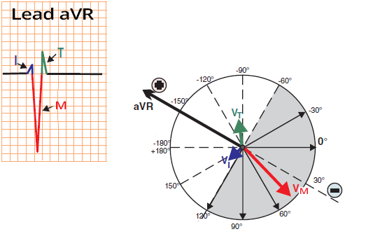
aVR Lead

Heart axis determination in positive hemisphere of aVR limb lead

aVR Limb Lead


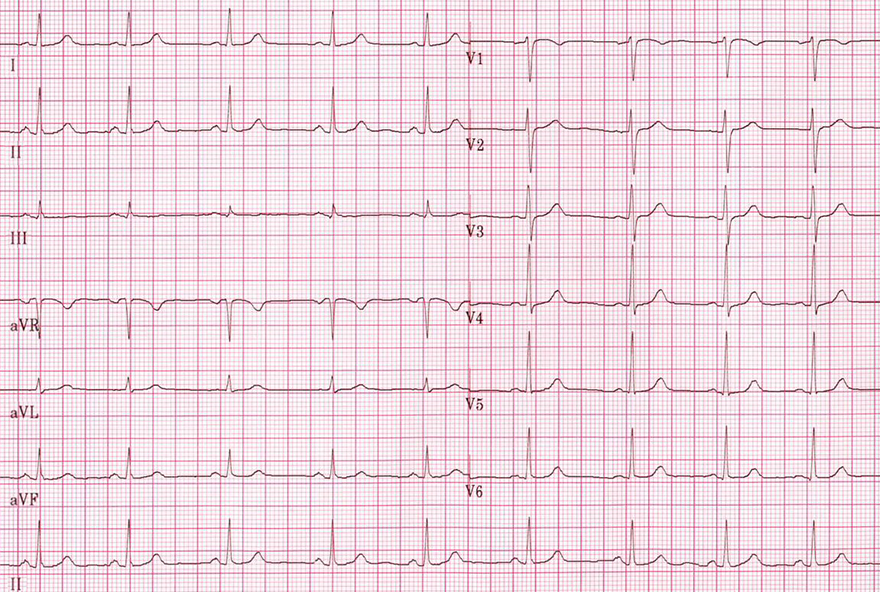
12-Lead ECG and the Main Heart Vector

  • The main heart vector creates the largest deflection on the 12-lead ECG
    • If it points toward the lead (R wave)
    • If it points away from the lead (S wave)
  • The electrical axis of the heart is determined by the direction of the main electrical vector in the limb leads

  • The QRS complex on the ECG shows the depolarization of the ventricles
    • In each ECG lead, it looks different
  • Because each lead "views" the vectors from a different angle
    • The vectors are always projected onto the electrical axis of each ECG lead
  • The images show ventricular depolarization (QRS complex)
Determination of the heart's electrical (QRS) axis in the frontal plane

Limb Leads


Determination of the heart's electrical (QRS) axis in the horizontal plane

Chest Leads


Heart axis determination during sinus rhythm on ECG strip

Sinus Rhythm


Sources

  • ECG from Basics to Essentials Step by Step
  • litfl.com
  • ecgwaves.com
  • metealpaslan.com
  • medmastery.com
  • uptodate.com
  • ecgpedia.org
  • wikipedia.org
  • Strong Medicine
  • Understanding Pacemakers


šípka späť

Electrical Axis of the Heart

Heart electrical (QRS) axis

Ventricular Depolarization

  • The ventricular myocardium depolarizes gradually
  • Depolarization creates an electrical vector
  • The more cardiomyocytes depolarize
    • The larger the electrical vector becomes

  • Summation Electrical Vector
    • Each cardiomyocyte creates a vector during depolarization
    • The common direction of vectors during depolarization
      • Is referred to as the summation electrical vector
  • Summation Vector of the Left Ventricle:
    • Is the resultant direction of depolarization vectors
      • Of all cardiomyocytes in the left ventricle
    • Is the largest vector
      • Because it involves the depolarization of the largest mass of myocardium
    • Its direction determines the electrical axis of the heart
  • The summation vector during ventricular depolarization

Mean frontal plane electrical QRS axis

Electrical Axis of the Heart

  • The ventricles depolarize gradually
  • First, the thin ventricular septum is activated
    • A small septal vector (VS) is created
    • Q wave
  • Next, the massive left ventricle is activated
    • A large main vector (VH) is created
    • Simultaneously, the thin right ventricle is also activated
      • The small right ventricular vector
      • Has no effect on the direction of the main vector
    • R wave
  • Finally, the base of the left ventricle is activated
    • A small terminal vector (VT) is created
    • S wave
  • Vectors should be imagined in 3D space
    • ECG leads record the vectors over time

  • The electrical vector of the left ventricle
    • Is the largest
    • Referred to as the main cardiac vector
    • Its direction determines the electrical axis of the heart

Heart axis vector during ventricular depolarization

ECG Leads

  • An ECG recording has 12 leads
    • Limb leads (I, II, III, aVF, aVL, aVR)
    • Chest leads (V1-V6)
    • Each lead "views" the vectors from a different angle
  • Leads "view" the electrical center of the heart
  • If the electrical vector points
    • Toward the lead on the surface - a positive deflection occurs
    • Away from the lead on the surface - a negative deflection occurs


Heart axis vector with ECG leads

Limb ECG Leads

  • They "view" the heart in the frontal plane
  • Each lead has a different node
  • All lead directions are from the electrical center of the heart
  • Electrical axis of the heart
    • It is the direction of the main vector in the frontal plane
    • Determined only by the limb leads:
      • (I, II, III, aVF, aVR, aVL)

Frontal plane electrical QRS axis and limb leads

Electrical Axis of ECG Leads

Lead axis and determination of the electrical axis of the heart

  • Each ECG lead has its own electrical axis
  • The main cardiac vector projects onto the electrical axes of all ECG leads
    • Each electrical vector of the heart projects onto the electrical axes of ECG leads
      • However, the cardiac axis is determined solely by the main electrical vector (from the depolarization of the left ventricle)

  • When determining the electrical axis of the heart, we only consider
    • the limb ECG leads (I, II, III, aVF, aVR, aVL)


Mechanism of determining heart axis via QRS complex deflection

Positive and Negative ECG Deflections

  • The cardiac electrical vector
    • must always project onto the electrical axis of the ECG lead

  • Positive ECG deflection occurs
    • If the vector points towards the surface electrode (+)
  • Negative ECG deflection occurs
    • If the vector points away from the surface electrode (+)


Heart axis principle with ECG electrical axis lead

Size of the ECG Deflection

  • The size of the ECG deflection
    • depends on the angle between the vector and the ECG lead axis

  • The smaller the angle
    • the more directly the vector points towards the electrode (+)


Perpendicular voltage vector and determination of heart axis

Isoelectric ECG Deflection

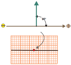
  • If the vector is perpendicular to the electrical axis of the lead
    • then no ECG deflection occurs

  • However, the electrical vector is "viewed" by 6 limb ECG leads
    • Each ECG lead has a different direction for the electrical axis
    • The same vector is never isoelectric in all leads


Perpendicular electrical vector and neutral plane. Determination of heart axis

Neutral Plane

  • When a perpendicular electrical vector
    • Is rotated in 3D space around the electrical axis of the lead
    • It creates the neutral plane of the given ECG lead
  • Every vector in the neutral plane
    • Projects onto the electrical axis of the ECG lead as a single point
    • No deflection appears on the ECG

Positive and Negative Hemispheres of ECG Leads

Positive hemisphere for lead I. ECG deflections will be positive if the resulting heart vector is in this hemisphere

Neutral Plane of Lead I


Heart axis determination with electrical vector negative deflection

Negative Hemisphere and Negative Deflection

  • Negative deflection occurs
    • Whenever the vector points away from the (+) electrode
    • The electrical axis of the lead continues beyond the electrical center of the heart (-)
  • Size of the deflection
    • Depends on the size of the vector that is projected onto the electrical axis of the ECG lead
    • Does not depend on the distance of the vector from the (+) electrode
  • Both vectors in the image produce the same ECG deflection


Heart axis determination with electrical vector positive deflection

Positive Hemisphere and Positive Deflection

QRS Complex and Electrical Heart Axis

  • During ventricular depolarization, 3 main vectors are formed
    • Initial vector (Q wave)
      • Depolarization of the septum
    • Main vector (R wave)
      • Depolarization of the left ventricle
    • Terminal vector (S wave)
      • Depolarization of the base of the left ventricle
  • The vectors are simultaneously "viewed" by the ECG leads
    • However, each lead "views" the vectors from a different angle
    • Each vector is projected onto the electrical axis of the ECG leads

  • The electrical axis of the heart is determined by the direction of the main electrical vector
Heart axis vector during ventricular depolarization

I Lead

Heart axis determination in positive hemisphere of I limb lead

I Limb Lead


aVF Lead

Heart axis determination in positive hemisphere of aVF limb lead

aVF Limb Lead

  • The white semicircle represents the positive hemisphere
  • aVF lead "views" vectors from an angle of 90°
  • Vectors are formed sequentially
    1. Septal (directed towards aVF lead)
    2. Main (directed towards aVF lead)
    3. Terminal

aVR Lead

Heart axis determination in positive hemisphere of aVR limb lead

aVR Limb Lead


12-Lead ECG and the Main Heart Vector

  • The main heart vector creates the largest deflection on the 12-lead ECG
    • If it points toward the lead (R wave)
    • If it points away from the lead (S wave)
  • The electrical axis of the heart is determined by the direction of the main electrical vector in the limb leads

  • The QRS complex on the ECG shows the depolarization of the ventricles
    • In each ECG lead, it looks different
  • Because each lead "views" the vectors from a different angle
    • The vectors are always projected onto the electrical axis of each ECG lead
  • The images show ventricular depolarization (QRS complex)
Determination of the heart's electrical (QRS) axis in the frontal plane Determination of the heart's electrical (QRS) axis in the horizontal plane

Limb Leads

Chest Leads


Heart axis determination during sinus rhythm on ECG strip

Sinus Rhythm


Sources

  • ECG from Basics to Essentials Step by Step
  • litfl.com
  • ecgwaves.com
  • metealpaslan.com
  • medmastery.com
  • uptodate.com
  • ecgpedia.org
  • wikipedia.org
  • Strong Medicine
  • Understanding Pacemakers